
A connector can fit correctly while two repaired signal terminals occupy the wrong positions. A communication fault after connector work needs a pin-assignment check.
Interpreting the evidence
Use the wiring information for the exact vehicle and connector view. Compare cavity numbers, wire repairs and the point from which the drawing is viewed. An apparent colour match is weaker evidence than verified terminal positions, especially when a replacement pigtail uses different colours.
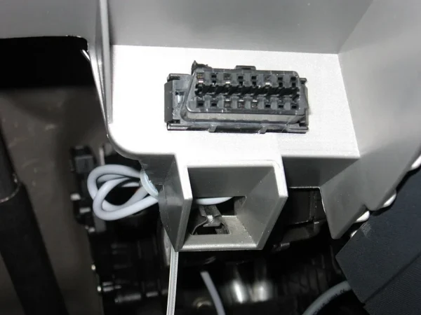
Keep this evidence
Send photographs showing the cavity numbering and the repair invoice alongside the complete scan.
Recheck the repaired circuit before condemning the controller. Terminal identification and electrical measurements belong to a controlled workshop procedure.
Speak to AXION
For CAN-bus and vehicle-network diagnostics, send your vehicle details and fault report. Workshop assessment is in Didcot, Oxfordshire. Suitable postal or remote work is confirmed before booking.
Technical background from Texas Instruments. The referenced design explains the principle; the vehicle-specific procedure determines the repair.
Related reading — A CAN transceiver left in standby can look like a dead ECU. Browse all vehicle-electronics diagnostic notes or return to the repair library.