
The scan tool says an actuator is commanded on. A voltage trace looks plausible. The component still does not work. Before blaming the ECU or the actuator, ask what has actually been measured at the circuit.
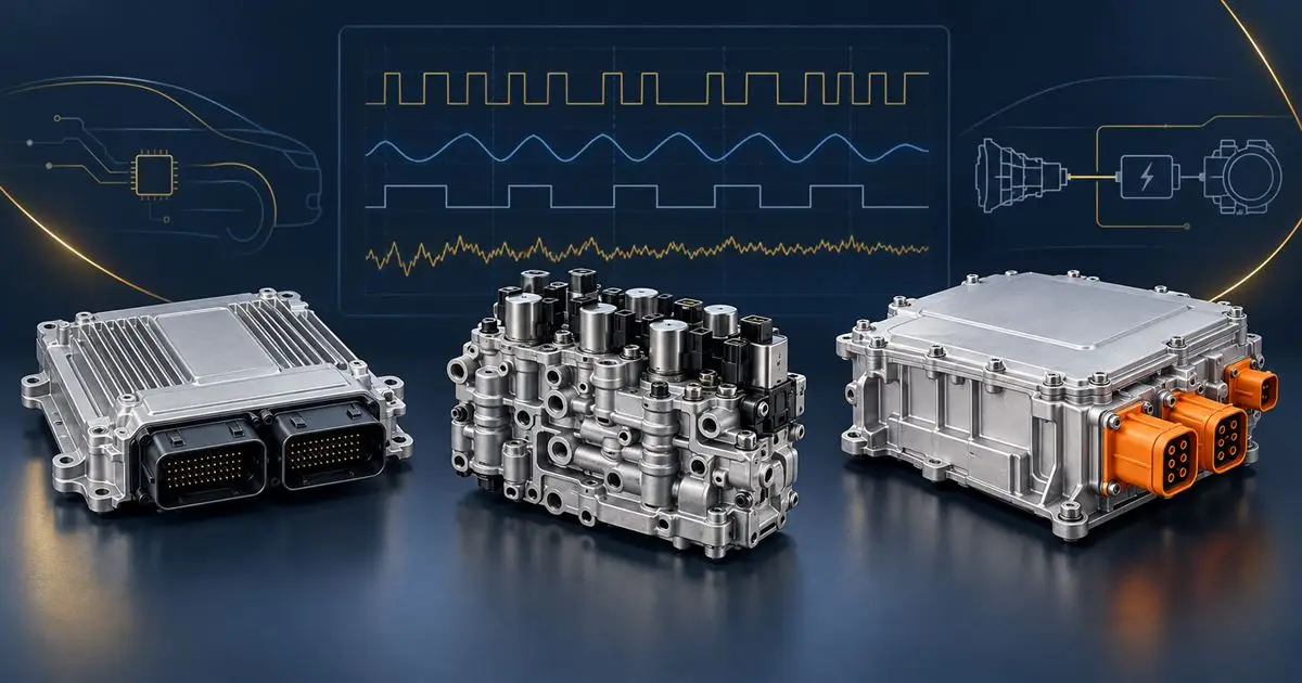
Pico’s connection guidance explains that a normal-looking control voltage does not necessarily prove the load is drawing current. It recommends considering current measurement for suitable actuator circuits and choosing test points that answer the diagnostic question. It also highlights the value of checking whether a sensor signal reaches the ECU correctly. Read Pico’s measurement guidance.
Make the capture useful to someone else
For an AXION enquiry, include channel names, units, the operating state and which component was commanded. Save the original capture where possible, plus a screenshot showing the relevant event. If a comparison trace is used, identify the vehicle and conditions it came from.
Avoid a cropped waveform with no scale or circuit description. “Looks noisy” is an observation; the next question is whether the noise is meaningful at that test point and under those settings.
Keep the test proportional to the question
A wiring diagram, a sound connection method and a clear hypothesis matter as much as the tool. Select equipment and accessories suitable for the circuit, and follow the vehicle and instrument procedures. A guide about low-voltage actuator testing is not permission to connect ordinary scope leads to an EV high-voltage circuit.
This article describes diagnostic methods, not an inventory of equipment owned by AXION or a promise that every ECU can be bench-tested. Send the findings for an electronics assessment enquiry or use garage and trade support.
Reviewed September 2026. Use the complete manufacturer-specific fault description and vehicle repair information.